Sensing Current Below the Threshold

At Functional Devices, Inc., we manufacture multiple types of current sensors. We have current switches, current transducers, and relay/current sensor combo devices, and there are plenty of variations of each. These options cover most applications where current sensing is required. However, there are increasing instances of loads that draw low current, especially with the prevalence of Electronically Commutated Motors (ECMs) and LED lighting. Sometimes these currents can be lower than the threshold for a current switch, but fortunately, there is a simple technique that may solve this problem.
When a conductor is passed through the aperture of a current switch, the current switch “sees” the current flowing through the line. If the same conductor is passed through the aperture two times, what the current switch “sees” is multiplied by two. This can be repeated as many times as the conductor can physically fit through the aperture, assuming the rating of the current switch is not exceeded.
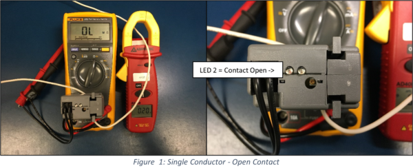
For an example, we will use our RIBXGTA current switch. The RIBXGTA has a minimum current sensing threshold of 0.75 Amps. Looking at Figure 1, the conductor is passed through the RIBXGTA a single time. The ammeter shows a current through the conductor of 0.2 Amps. This is not enough to trip the current switch, and this is shown on the display of the multimeter as an open contact. That is also shown by the dimly lit LED on the RIBXGTA, which is indicating the current is below the threshold.

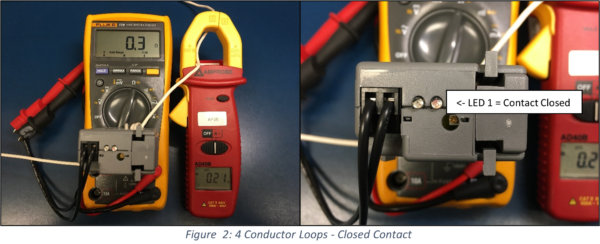
Now, looking at Figure 2, the conductor is passed through the RIBXGTA four times. If we apply what we learned above, multiplying that 0.2 Amps by four loops of the conductor, the current switch should “see” 0.8 Amps. This is above the minimum threshold of the RIBXGTA, and the output contact should close. Indeed, it does. This can be seen on the multimeter as a low resistance reading from the output contact. Also, the other LED on the current switch is lit, and this LED indicates a closed output contact.

This technique can be applied to any current sensing device, as well as transducers. For example, the RIBXGTV5-10 is a current transducer that outputs a 0-5 Vdc signal, that is proportional to a 0-10 Amp current being sensed. If the current carrying conductor is looped through the aperture two times, the output will not be a 0-5 Vdc signal, which is proportional to a 0-5 Amps of current.
Please contact us if you have any questions about this technique, or if you have any other questions about our products.
